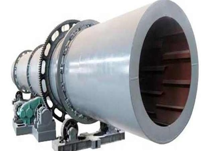
Horizontal Vertical Continuous Casting Production Process
PRODUCTS THE PROCESS To begin, the casting crucible is furnacefed by an underpouring method from a continuous melting source. The molten metal is maintained at the correct holding temperature in the crucible, which is completely enclosed. Any dirt, dross or gases present rise to the top of the melt and are left behind in the casting process.